
Multi Pattern Components
Overview
Multi Pattern is a command for patterning components in groups using constraints, with options to create new assemblies and define complex pattern groups. This tool allows you to control the arrangement and spacing of components using a flexible pattern string, making it ideal for advanced assembly design and automation.
Multi pattern is a group of patterned components using constraints and optionally placing the pattern into a new assembly. In addition, Multi patterns allow you to define groups of patterns. The pattern is controlled by an input pattern string which is a series of comma delimited patterns.
If Create Assembly is checked, a new pattern assembly is created using the assembly name provided and the BOM structure is set to phantom. The new assembly pattern can be modified by using the "Assembly Tools Configure Component" command.
When not creating an assembly and multiple items are selected for pattern, you have the option to keep components separate or to combine them into a single demoted assembly before creating the pattern.
You can add and remove parts from the new assembly as you would normally. However, if you edit with Configure Component, a new component pattern will be created using the first "MPComponent" found and delete the remaining "MPComponent". Any other components you have added (or renamed) will remain unchanged.
When creating constraints, each sub pattern can have all of its components constrained to either its first component (base) or the previous component. The first element of each sub pattern is always constrained to the last element of the previous pattern.
Multi Pattern Format:
Spaces @ Distance, Spaces @ Distance, ...
Where "Spacing @" is optional and if not provided 1 space is the default.
Distance is any valid Inventor expression that evaluates to a length number, or a three part expression separated by a colons.
The three components of the distance are evaluated and the values are the components of the offset ignoring the Pattern Direction.
Distance Expressions
There are two types of distance expressions: an expression that evaluates into a single value, or an expression that contains three parts separated by colons.
Single Value Distance Expression
A single value expression may contain any valid Inventor input expression, including built-in functions, prefixes, parameter names, algebraic operators, and units. Note the expression uses a semicolon to separate the function parameters length1 and length2. This is the same format used in Inventor input.
2 in + 3 * cos(angle) + max( length1 ; length2).
This will offset the components by the value of this expression, and assign the expression (possibly adjusted) to the constraints. Note the expression is assigned to the constraints, not the result value. This is useful if the values of the parameters are updated at a later time the pattern will adjust accordingly.
If the pattern direction is along the X axis for example and the component coordinate system matches the assembly coordinate system, the expression is assigned to the X constraint, and both the Y and Z are set to 0. If however the component coordinate system is rotated, the constraint expressions are adjusted to account for the rotation in order to maintain the requested offsets. In addition, if the offset direction is not along one of the coordinate system axes and a custom direction is entered, the constraints are again adjusted.
Three Part Distance Expression
The second type is a three part expression which represents an absolute offset in each of the x, y, and z directions . For example if you want an offset 10 units in the x direction, 20 units in the y axis direction, and 30 units in the z direction you would enter "10 : 20 : 30". In this case, the "Pattern Direction" is ignored since we have all three components of the offset. Like the single distance expression, each of these three components may contain any valid expression. For example: "10 * Offset + 2 in : 20 * Offset + 3 in : 30 * Offset + 4 in.
Note the difference between applying a direction and single offset expression and applying a three part expression. If the direction is 1, 1, 1 and the offset is 10 the component will be offset equally in the x, y, and z directions and the origin of the component will be 10 units from original. Note each of the plane-plane distances will not be 10, these are all less to allow for the absolute distance from origin to origin to be 10 as requested.
The second method is to apply an absolute offset in each direction by supplying a three part coordinate offset. In this case an offset of 10 : 10 : 10 (remember the direction is ignored in this case) would provide a plane-plane distance of 10 units as requested. However, in this case the distance from origin to origin would be 17.3 - the square root of (10^2+10^2+10^2).
Examples
Example Multi Patterns:
- 5 @ 24, 32mm + 5in, 2 @ 2'-11 3/4" + 36in, 2 @ 12
- 6, 10 @ 12, 6
- 5 @ cos(angle) : sin(angle) : 0, 24 in, cos(angle), max(length1 ; length2)
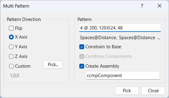
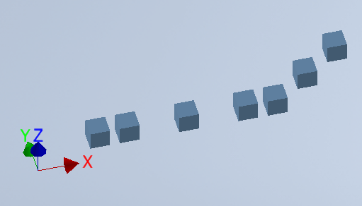
In the clip below, a pattern is created with 4 spaces at 200, 1 space at 120x 0y 24z, and an additional space at 48.
In the example below, the cube is patterned 1 @ 15, 2 @ 30, 1 @ 15, 2 @ 15:0:15.
Pattern Direction
Pattern direction values are ignored when the distance value is a 3 part input for the x y and z offsets.
Flip is used to flip the direction of the pattern in the opposite direction
X, Y, Z Axis: select the axis for a direction to pattern the components
Custom: you may click the pick button to select an edge for a pattern direction, or you may enter a three number coordinate for the direction.
Pattern
Pattern is the pattern definition (spaces and distance) for the multi pattern.
Constrain to base constrains all additional components back to the first component in the pattern
Combine Components is used when multiple components are selected for the pattern. In this case, you have the option to combine the components into a single component prior to creating the pattern.
Create Assembly will generate the pattern in a new sub assembly using the assembly name provided. This new pattern assembly can be edited by using Configure Component.
Dialog Box Input
Pattern String
Enter the pattern definition using spaces and distances (e.g., 5 @ 24, 2 @ 12).
Pattern Direction
Select X, Y, Z axis or pick a custom direction for the pattern.
Offset
Specify offset values for x, y, and z directions. Use single or three-part expressions.
Combine Components
Option to combine selected components into a single component before patterning.
Create Assembly
Check to create a new assembly for the pattern. Enter the assembly name.
Constrain to Base
Constrain all patterned components to the first component in the pattern.
BOM Structure
Set the BOM structure to phantom for the new assembly.
Edit Pattern
Edit the pattern after creation using the Configure Component command.